- Office - 904-261-3327 or 800-395-8953
- Fax - 888-272-0876
LOUVERS
Depending on the Design Pressure loading, an architectural or hidden vertical mullion on a long run of louvers may be an option which would allow for a continuous look.
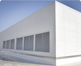
Louvers serve the purpose of providing ventilation in defining spaces for applications such as mechanical rooms, emergency generator, air intake and exhausting, as well as for screening open mechanical equipment such as cooling towers and AHU installations.
Louvers have the option via their applied finishes to create an aesthetic impact on the overall color scheme for a building. Using Kynar (70% PVDF) applied finishes, available in two, three, and four coat versions, various colors are available to highlight or contrast as needed. Beneficial to the use of this finish option is the extended finish warranty offered further enhancing benefits to the project’s owner.
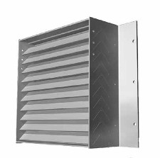
A combination louver typically blends together several features in a common frame. One example is pairing an exterior fixed Drainable blade with an operable blade interior section, thus creating a built-in operable damper effect. Another is to, in a common frame, pair exterior fixed Drainable blade with a vertical rain resistant blade segment mounted to its interior. Both would need to be verified to its efficiency to resist wind driven rain via testing and listing of the AMCA 550 standard.
Depending on the model, louver units have maximum sizing per unit, so for larger openings, individual units may be stacked horizontally or mulled vertically to fit the opening’s dimensions. The type of mullion will depend on the Design Pressure of the structure.
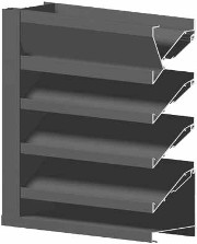
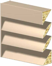
A Drainable blade louver design allows the rain to be directed to the exterior and shed safely thus minimizing the infiltration of water to the interior. The effectiveness is a function of the blade design, blade depth and angle of the blades in the frame. Testing via AMCA 500-L will give the basic ratings for air infiltration, airflow point where water leakage begins, and flow at differing pressure drop levels.
FEMA rated louvers are those which are designed to meet higher wind and debris impact requirements as published by FEMA for use in critical facilities including areas with historical hurricane and tornado storm impacts. The requirements exceed Design Pressure requirements typically found in model Codes as well as requirements for Basic and Enhanced debris impact. The base ratings would require differing design and overall depths, thus making this a more costly option. One model, as an example, is designed and rated to meet 200 PSF Design Pressure loading while also resisting impact from a 15 pound missile impacting at a speed of 146 feet per second (100 MPH). More information on this is available on FEMA Publication P-361.
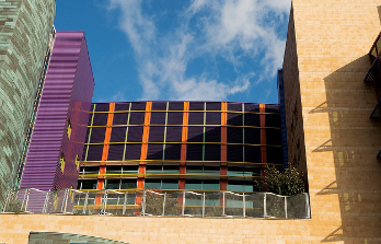
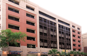
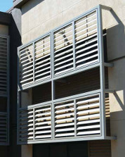
Mulled louvers are used to both provide ventilation and a finished look to the garage portion of the building. Combined with a choice of blade styles and finishes, the louver application can provide contrast and highlight the overall design.
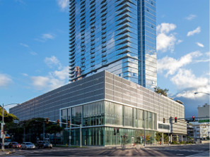
On this application for the upper floors of the building at which parking is located, louvers are stacked vertically to span the multiple floors while also being vertically mulled using appropriate mullion sections to handle the Design Pressure. The application provides needed airflow as well as an aesthetic look.
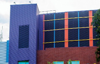
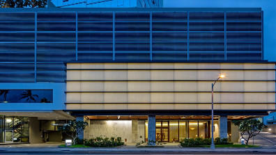
The mulled louvers for this mechanical space provide ventilation for installing equipment as well as blend in with the look adjacent exterior panels give to the structure.
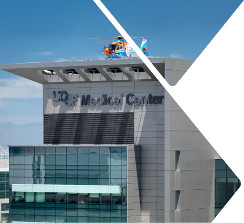
In this example, mulled louver units provide ventilation for both the designated parking floors and the mechanical equipment floors of the structure. Due to the span and Design Pressure loads, custom mullion sections were used to meet the requirements.
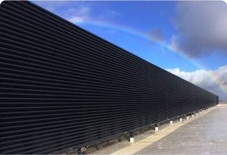
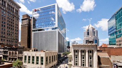
In this garage application, louvers are used to complement the design of adjacent structures as well as providing limited weather protection from rain to the interior space. In applications were louvers are used over the whole facade which may include open spaces as well as structural wall components, the louver may be applied to the exterior in a continuous manner with those sections which are over the exterior wall construction featuring a blank-off panel on the back side of the louver to give a more aesthetic look.
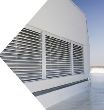
Louver application for a rooftop mechanical room featuring mulled louvers.
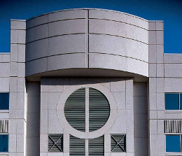
Louvers also be fabricated to select shapes such a circles or circle segments, triangular shapes, arc tops and others. Specific restriction on sizing and possible shapes, particularly in High Velocity Hurricane Zone (HVHZ) areas, may apply. In addition to wind driven, rain resistant profile, AMCA standards note that any testing done of those units, which is based on a rectangular shape, are not applicable to shaped applications.
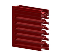
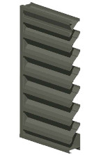
This vertical perspective sectional drawing shows a blade design used in maximizing resistance against wind blown rain. It may be used for horizontal and vertical blade models, while other blade designs are used in Drainable, acoustic, combination and other louver models.
Acoustic louvers differ in construction via the use of filler materials in blades as well as special construction to mitigate the transmission of sound. Due to various differing requirements, the louver units are available with different blade styles, differing overall depths, and also feature different acoustic performance characteristics which are listed in reference to specific sound wave frequencies. In order to select the proper units for a project, input from a specialist in acoustic may be required at the design stage and that information included in the outline for specifications.
SUN SHADES
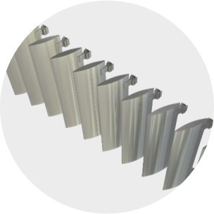
This illustration shows the typical airfoil blade design which is one of the most popular options selected for sunshade units. The airfoil design is sleek and blends in with most facades. It comes in different depths and coupled with the selected angle to its mounting in the brackets, it can solve many shading requirements.
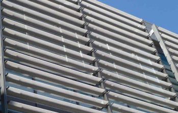
Sunshades can be applied directly to the substrate or in conjunction with an exterior wall application such as this one which features a curtain wall system. Engineered for proper support, the sunshade modules are installed onto the reinforced sections. Typically, sunshades must be provided with PE sealed drawings and calculations as the applications differ and no two are identical. This makes a “standard” “pre-engineered” system difficult as it may not fit for other applications, combined with the blade, depth, facades and installation into different substrate constructions.
Most popular are Kynar (70%) PVDF finishes which are available in a number of finishes including matches for clear and colored anodized finishes. These two, three and four coat systems cover the gamut of designer color schemes and carry extended finish warranties.

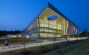
This photo shows a project with cantilevered sunshades on the upper exterior areas whose depth allows for shading of the glazed openings during the period with extreme sunlight and glare. The angle of the blades as well as depth of the unit can be engineered to fit differing requirements of a project.
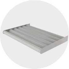
This illustration shows a sample of a cantilevered sunshade featuring airfoil style blades. The angle at which the frame is attached to the substrate of the structure can serve for various purposes including design impact and enhanced daylight or shading effect.
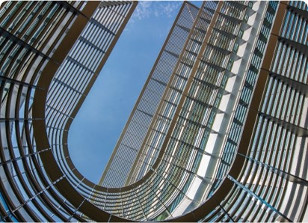
The buidling design may require custom engineered application such as the curved segments which are illustrated on this project photo. The designer wanted to wrap the sunshade around the atrium space created by his design, so suitable elements were selected, cuved and assembled as modules for ease of installation.
Note that not all components offer the flexibility to be curved and create a clean, crisp solution, so consult with us for evaluation of your concept, so we may offer suggested options.

This photograph taken from a different quadrant more clearly shows the sunshade application, including the curved segments which are installed in the exterior Atrium area.

This photo more closely depicts the cantilevered sunshade at the roof area, and also shows the structural elements required to execute the design at the corners.
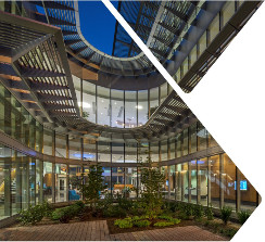
This photo of the curved sunshade application better illustrates the effect of the sunshade’s design on the exterior Atrium space created by the designer for this project.
This example shows a custom engineered, cantilevered sunshade project, which met the designer’s s need for sunlight shading using specific blade angles. In addition, factory supplied sealed PE drawings and calculations showed that the assembly met Code required wind uplift design criteria as well as validated the fastening scheme to the substrate. Note that Code requirements make such engineering information a requirement for projects, and this can either be supplied by the engineer of record or supplied as part of the scope by the manufacturer.
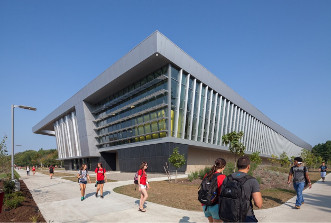
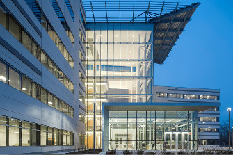
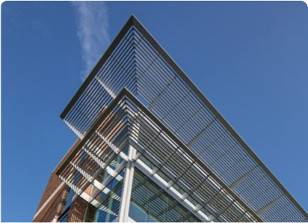
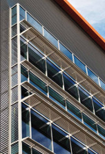
The striking design for this University featured on one elevation sunshade units horizontally at the glazed wall systems, while the other elevation featured the sunshades applied vertically to better control the daylight based on the building’s orientation.
The striking design of the building is complemented by the sunshade application which blends in with the installed curtain wall system.

On this sunshade application the designer wanted to mimic a freestanding canopy look while also maintaining free airflow and sun control.
This project’s photo of the sunshades features at the upper level an extended depth projection and also illustrates the factory fabricated corner condition which allows for a cleaner look. In such conditions, the plant fabricates the corners as modules, eliminating the field assembly of mitered segments, thus maintaining the finished look as well as lowering installation costs and field assembly issues.
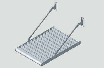
This illustration depicts the use of rods for support of an airfoil style sunshade unit. Depending on the size, structure and design pressure requirements, this approach may be a suitable solution for specific project applications.
This close up photo shows the use of the airfoil style blades as well as round fascia creating the desired effect.
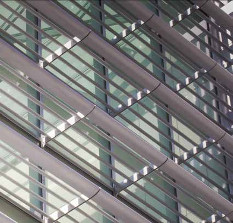
The photo illustrates an offset application where the sunshade is used vertically and spaced away from the exterior wall. This was a unique solution for this opening due to the building’s location and orientation.
This sunshade application documented in this photo shows the integration of the sunshade application to the exterior glazed wall system using structural offset support elements, and spacing from the vertical plane to create a more effective shading as well as finish look for the project.